Control the Big Stuff
I have always been amazed that a little fragile computer chip, that could easily fry from static electricity, could control a massive 400 amp solenoid to activate a dump load for a massive wind turbine. I'm just as impressed when that little processor switches on five 60 watt light bulbs.
In this fourth and final installment, I'll be discussing how to pull this kind of thing off. Before you know it, you'll be controlling the big stuff.
Theory
The Arduino can only handle a maximum of 40 mA of current on its output. This would work for a small relay, well, except for the fact that the Arduino's output is only a maximum of 5 volts. And, I really hate to push the Arduino like that. It just generates a bunch of heat and is more likely to overheat with time. I love electronic circuits that run cool and efficiently. You know, those circuits that are reliable, not those circuits that fail after 2 days of use.
So, what we need is a way to take a 5 volt signal from the Arduino and input it into something that has a large resistance/impedance. That way, very little current is drawn from the Arduino and it continues to run cool. The trick is transistors.
Transistors
There are many types of transistors, but I will just talk about 2 here; the bipolar junction transistor (BJT) and the MOSFET. And, just to keep it even simpler, I'll only refer to the NPN type of BJT and the N-channel MOSFET.
Basically, a transistor is just a switch. If you apply a small current or voltage (depending on which type) to the gate/base, it allows current to flow between the other two connectors.
BJT
The BJT of this size can switch about 500-600 mA of current max, but I wouldn't recommend that because it will get very hot. If you can keep it to about 150 mA or less then that would be perfect. A typical relay that this could drive would draw about 70-120 mA, which is perfect for this transistor. The circuit might look something like this.
To limit the current coming out of the Arduino into the base of the transistor, I used a 1k resistor. Since 5 volts divided by 0.005 amps equals 1,000, I used a 1k resistor. The transistor will turn on using just a 1 or 2 mA or so. Even at 5 mA on the base, that should still switch at least 150 mA through the junction.
I also wanted to limit the current to the 12 volt relay from the battery. I picked 80 ohms to limit the current to 150 mA. The 80 ohm resistor isn't standard, so you can use a 81 ohm at 5% tolerance. Also, keep in mind that at 150 mA, the resistor would be dissipating 1.8 watts. You would have to use a 5 watt power resistor. The better option would be to use a fuse, maybe a 250 mA rated fuse.
MOSFET
Note that the MOSFET can be used the same way the BJT is used. The gate on the MOSFET has a high impedance so the 1k resistor isn't technically needed. But, I like to keep it just in case, mainly to protect the Arduino if something is not connected right, or the transistor shorts out internally after a failure.
I also placed a diode across the relay coils. When the relay turns off, the magnetic field collapses and a high voltage reverse pulse is released. The diode will absorb that pulse to protect the transistor.
But, you may want to just use the MOSFETS as a relay and skip the whole "moving parts" idea. Typical MOSFETS can handle 10 to 80 amps or so. They need to have good heat sinks attached for heat dissipation. You can parallel as many as practical. If you had a MOSFET that could handle 30 amps, then using 10 in parallel could handle 300 amps. You get the picture.
Small 5 volt relays
There is another option that should be mentioned here. A small 5 volt relay is available that can connect to the Arduino. If you use these, make sure they have (or you use) a freewheeling diode and optocoupler to protect the Arduino.
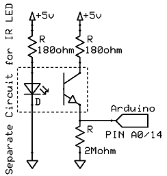
This particular example can be cycled 100,000 times and switches 10 amps at up to 250 VAC. The optocoupler ensures that the Arduino is protected. It basically connects the Arduino to the relay via light. It uses an LED that activates a photo-transistor, all inside a small chip. It also ensures that only a few milliamps will be drawn from the Arduino output .

I would not recommend paralleling relay boards, though. When they activate, they don't turn on at exactly the same speed. This means that one may turn on a few micro seconds before the rest. That one set of electrical contacts will be temporarily carrying the entire load. Let's say that you have a 100 amp load and you are using 10 relays each capable of 10 amp switching. Then, for those few initial micro seconds, one relay is carrying 100 amps. This will start to burn out the contacts, or worse, weld the contacts closed. That would be very bad for a dump load controller. It would drain your batteries and kill them. And we don't harm batteries here...not here...ever.
IF YOU'RE INTERESTED IN LEARNING ELECTRONICS
Then Take A Look At This!


