Measuring RPMs
Let´s face it, sometimes we just need to know how fast something is spinning. Sure, we can eyeball it to some extent, up to a few hundred RPMs, but after that it becomes a little bit hairy. And, even then, it isn´t very accurate. The Arduino is perfect for quick and easy projects like this, when you just need to do some quick tests.Measuring RPMs is basically just counting pulses per revolution over a given time frame and extrapolating out to one minute. But, what pulses and how do we do it? There are many ways I can think of, but two very common methods are used; hall effect sensors and optical (photo interrupters). So, let´s dive right in.
Hall Effect Sensor
A hall effect sensor works on changes in magnetic fields. Basically, if you have a magnet attached to the rotating object that you want to measure, every time it passes the hall sensor, a voltage is created on the output. The Arduino can detect the change and count it as a pulse. If you get 50 pulses per second, for example, that equates to 3,000 RPMs.
You can use a circuit board like this one and it will work fine. You could also use the hall sensor directly, as shown below. The 10k resistor is a pull-up resistor to keep the normal out put state high or close to 5 volts in this case. When the hall sensor is triggered, the output goes down.

Something to keep in mind is balance. Putting one magnet on a high speed rotating device might make it out of balance. You could consider putting two magnets on the rotor across from each other to balance it. Opposite poles could be pointing out to make the changes in poles more distinct and to give better accuracy.
Optical Photo Interrupter
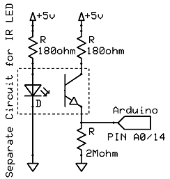
This one is like it sounds, you are interrupting a beam of light. Typically, these use a rotary encoder disc which are discs with slots cut out.
The optical sensor sits straddled over the disk. A built-in diode shines a light while a photo-transistor senses that light. An On or Off signal is then generated for the Arduino.
 |
| Image courtesy of utopiamechanicus.com |

IF YOU'RE INTERESTED IN LEARNING ELECTRONICS
Then Take A Look At This!
Then Take A Look At This!

This comment has been removed by a blog administrator.
ReplyDelete