Translate

Tuesday, December 13, 2016

How much does solar REALLY cost?


This is a video on youtube.com posted by LDSreliance. I thought it was an interesting topic and decided to check out the numbers myself. It has been a long time since I purchased solar equipment and prices have fallen quite a bit. In the video it breaks down prices based on 3 systems; Small (hobby), Medium, and Large.


This equates to $2.50 per watt for the panel and $12 per watt for the system. I decided to check on amazon.com to see how prices compared:

10 amp / 12 Volt charge controller = $11.99
12 Volt SLA Battery - 8 amp hours = $17.99
400 Watt / 12 Volt inverter = $23.48

I believe the wire connectors and mounts would be about $30 as stated. This means that the $120 price tag is conservative.

================================


This equates to $1.40 per watt for the panels and $3.20 per watt for the system. This is how the prices compared on amazon.com:

60 amp charge controller - 12 volts = $45
Batteries - 450 amp hours at 12 Volts = $700 ($350 each)
600 Watt sine wave inverter = $89
Wire, connectors, mounts, etc. = $100
TOTAL = $1,350

The price was a little higher than expected, especially the batteries. A better option might be to desulfate some forklift batteries and save lots of money. I explain how to do that in my wind power ebook.


=======================================


This equates to $1.00 per watt for the panels and $2.83 per watt for the system. This looks fairly close to me as well. I would probably use three of the 60 amp charge controllers at $45 a piece, for a total of $135 instead of $1,100. But, overall, I believe the video to be fairly accurate.


Wednesday, June 22, 2016

Solar Tracker


Making a solar tracker for a solar cooker or solar panels is easier than you may think. You could design one that uses a micro-controller or complex circuit. But, it can also be done with JUST small solar panels and a DC motor.

The concept is simple. You have two or four small identical panels that are each powerful enough to spin a small DC motor. There is a divider between the panels that cast a shadow when the unit is not pointing directly at the sun. The panel that doesn't have a shadow cast on it produces all the power and turns the motor. As the shadow starts to minimize, the other side's panel starts applying reverse current to the motor and slowing it down.

solar tracker circuit


You could have more than one panel each side, as shown below.

solar tracker circuit


Something to remember is that the motor will have to be geared down so the output is lower. Or you can find a geared motor, such as a windshield wiper motor. You could also use a smaller motor and just use a string wrapped several times around the spindle or capstan of the motor. The rest of the string would wrap around a wooden pulley or disk from both sides. And, of course, the string would be stretched taut.


IF YOU'RE INTERESTED IN LEARNING ELECTRONICS 
Then Take A Look At This!

Monday, June 20, 2016

Make your own powerful and simple alcohol stove


I uploaded a couple of videos testing this powerful alcohol stove and some people have asked for instructions on making this. It is very quick and easy to make. Have fun!

Richard

Wednesday, June 15, 2016

Weird way to furl a windmill

I was watching a video on youtube where supergokue1 was running a double windturbine on one mast and connecting the motors in series to get more voltage. The test didn't produce as much voltage as he had hoped, but I had an interesting idea about furling this windmill under higher wind conditions.

SuperGokue1 on Youtube.com

The idea involves a physics concept called gyroscopic precession. This is a phenomenon occurring in rotating bodies in which an applied force is manifested 90 degrees later in the direction of rotation from where the force was applied. We use the right hand rule to determine the torque direction or spin vector.


Applying the right hand rule to the double windmill, based on direction of blade rotation, means that the spin vector is a force acting outward towards the wind. Each blade set is doing that so both forces are balanced. But, what if you design one of the blades so it spun in the opposite direction? And, then, you make the tail smaller? 

The result would be that higher winds will cause the windmill to yaw out of the wind slightly. This will slow the blades down, then gyroscopic procession will decrease as the blades start to spin back into the wind and the process repeats...until a sweet spot is found. This should work nicely for small fast spinning wind turbines. This should protect them in higher winds. Just imagine 40 mph winds while the wind turbine is furled sideways at a 45 degree angle and still producing safe power.

Sunday, June 12, 2016

Survival Lilly Survives Canada

Survival Lilly came to Canada....and survived. She spent about a week in the bush, practicing her bushcraft and survivalist skills. The helicopter picked her yesterday, and yes, she was in one piece. Unfortunately, we have to wait a few days to see her video updates. I can't wait to see those.

We gave her a ride to the BC-Ferries terminal today. I have a nice Survival Lilly patch to show off now. But, don't worry, she left with a Canadian flag patch of her own. Now, she is off to her next secret survival spot to live the adventure. Rock on Lilly!


Friday, June 10, 2016

VAWT (Savonious) Wind Turbine Calculator

I have done some work on my VAWT / Savonious Wind Turbine Calculator. It allows you to enter parameters and compute power output, amperage to batteries or the grid, cut in speed, etc. The program can be found here.

You start by selecting a battery voltage; 12, 24, or 48 volts. Alternatively, you may select 120 or 240 volts for grid tie. Weather conditions default to "moderate", but you may calculate for summer or winter as well. This is important because the temperature and density of the air can have a profound effect on the generator's cooling and therefore its maximum power output.

You can then enter the overall blade width. This is the width of the turbine as seen by its profile, not just one blade. Then enter the blade height.

The Gear Ratio field is used when your generator needs more speed to produce a usable voltage. Wind speed is entered in miles per hour. The calculations are based on this wind speed.

Tip Speed Ratio (TSR) is how fast the tips of the blades move in comparison to the wind speed. A typical horizontal axis wind turbine (HAWT) is usually between 3 and 10 TSR. A typical VAWT such as a Savonious is about 0.8.

The Blade Efficiency field also represents the Power Coefficient. A well-designed 2-blade Savonious has about a 24% Power Coefficient. A 3-blade has about 15%, although it does have more torque and works better at less than 23 mph or so.

The motor/generator's amp, volts, and RPM rating are usually given by the manufacturer. The generator's efficiency is a little different. Typically, a permanent magnet DC motor with brushes is about 50%. A three-phase permanent magnet alternator is about 75%, and an AC induction motor is about 90% (used for grid tie).


Monday, June 6, 2016

White roof to help keep cool

I've said for years that we should have white roofs. There is really no reason to have an attic get 120 to 150F. Everyone is just used to the dark shingled roof. Some do the metal roofs, but they are more expensive in the short run. But, this idea is really creative. This guy named David found he could coat his roof with lime and water (whitewash) and it lasted for a few years. Who knows how long it would last, but at $14 for materials, you could coat the roof every few years and still save a ton of money.

Note that in the picture below that the roof could use a couple more coats. But, this was just a test and it proved to work very well, even though the roof wasn't completely white.


His results were fantastic; 8F to 10F cooler in the house and 30 to 40 degrees cooler in the attic. Now, imagine mixing this idea with the cheap air conditioning idea I talked about back in 2010.


read more about the story here...

Richard

Sunday, June 5, 2016

So hot, time to revisit cheap air conditioning

Been so hot lately, I just wanted to point out the cheap air conditioning post from a few years ago. Check it out.


Survival Lilly comes to BC

I recently had the great pleasure of meeting Lilly, from the Survival Lilly channel on Youtube. I gave her and her adventure guide (Randall from SurviveBC) a lift from BC Ferries. We stopped off at a great little restaurant in downtown Victoria called Vista 18. Panoramic views, good food, and interesting conversation made for a pleasurable afternoon.

Lilly is a survivalist, if you haven't gathered already. And she has traveled all the way from Austria just so she can take a helicopter ride out into the "bush" at an undisclosed location, away from the things of man. There, she will rough it for 6 days, alone, with only her camera to keep her company. He is a great listener, but the conversations are a little one sided.

She is out there now in the dark. Hopefully, she managed to get a shelter setup and maybe catch something to eat for dinner. We just won't know how things went until someone hears from her in 6 days. Fingers crossed.

Richard

Saturday, April 30, 2016

Off-grid Electric Arc Furnace

I found this on the King of Random youtube channel. It is very interesting and has lots of uses. This particular version uses two microwave oven transformers on 240 VAC. This outputs about 20 to 40 volts at about 40 to 80 amps.

But, instead of using transformers and wall power, what if you used two reclaimed car batteries wired in series? And, what if you charged them with solar? This would make for a great off-the-grid metal furnace. And, with car batteries and bigger electrodes, you could have a much bigger furnace.


Sunday, January 17, 2016

Battery Desulfator - Capacitive Voltage Divider

A few years ago, I posted this video showing my first crude battery desulfator.


This works like a champ, but I wanted to point out there are a few ways to make this safer. The one in the video had no protection and it put out up to 170 volts pulsed DC at 1.1 amps. This one MUST be connected to a battery when you turned the power on.

I wanted to make it safer and limit the voltage to about 55 volts. This is done without a transformer and uses just run-type capacitors. You could also use a transformer, but, hey...this is just interesting. Besides, you can swap out capacitors to get different currents. Also, a transformer isn't constant-current like this circuit.

Update - the fuse should be on the hot side.

The top capacitor basically controls the amperage. This one would be 1.1 amps at 120 VAC at 60hz. The bottom controls the voltage. If the bottom capacitor is rated the same as the top, then the output will be cut in half. In this case, there is 120 VAC coming in and the output will be one-third of the input, or 40 volts AC. Actual DC is 1.4 times the AC value, so the full-wave bridge's output will be 56 VDC pulsed at 120 times per second.

Here is a real-world example. Let's say you have lots of 25 MFD run-type capacitors that you picked up from the local HVAC shop. You could use 5 of them as shown below. This gives you one fifth the input voltage that goes to the rectifier.  If you start with 120 VAC, this gives 24 VAC to the rectifier. Multiply that times 1.4 and you get 33.6 VDC. This example could charge any lead-acid battery up to and including 24 volts with no problem. It would do it at 1.1 amps.
Update - the fuse should be on the hot side.

IMPORTANT: This is not a smart charger. It will keep trying to charge a battery and it is like the terminator, it will not give up. You have to monitor the battery voltage and fluid levels. You don't want to overcharge or dry out the cells. OR, you could use an Arduino to monitor the voltage for you and switch this circuit off with a relay.


Sunday, January 10, 2016

Arduino: Micro Processing Renewable Energy - Part 4 - Control the BIG stuff!

Control the Big Stuff

I have always been amazed that a little fragile computer chip, that could easily fry from static electricity, could control a massive 400 amp solenoid to activate a dump load for a massive wind turbine. I'm just as impressed when that little processor switches on five 60 watt light bulbs.

In this fourth and final installment, I'll be discussing how to pull this kind of thing off. Before you know it, you'll be controlling the big stuff.

Theory

The Arduino can only handle a maximum of 40 mA of current on its output. This would work for a small relay, well, except for the fact that the Arduino's output is only a maximum of 5 volts. And, I really hate to push the Arduino like that. It just generates a bunch of heat and is more likely to overheat with time. I love electronic circuits that run cool and efficiently. You know, those circuits that are reliable, not those circuits that fail after 2 days of use.

So, what we need is a way to take a 5 volt signal from the Arduino and input it into something that has a large resistance/impedance. That way, very little current is drawn from the Arduino and it continues to run cool. The trick is transistors.

Transistors

There are many types of transistors, but I will just talk about 2 here; the bipolar junction transistor (BJT) and the MOSFET. And, just to keep it even simpler, I'll only refer to the NPN type of BJT and the N-channel MOSFET.

Basically, a transistor is just a switch. If you apply a small current or voltage (depending on which type) to the gate/base, it allows current to flow between the other two connectors.

BJT


The BJT of this size can switch about 500-600 mA of current max, but I wouldn't recommend that because it will get very hot. If you can keep it to about 150 mA or less then that would be perfect. A typical relay that this could drive would draw about 70-120 mA, which is perfect for this transistor. The circuit might look something like this.

To limit the current coming out of the Arduino into the base of the transistor, I used a 1k resistor. Since 5 volts divided by 0.005 amps equals 1,000, I used a 1k resistor.  The transistor will turn on using just a 1 or 2 mA or so. Even at 5 mA on the base, that should still switch at least 150 mA through the junction.

I also wanted to limit the current to the 12 volt relay from the battery. I picked 80 ohms to limit the current to 150 mA. The 80 ohm resistor isn't standard, so you can use a 81 ohm at 5% tolerance. Also, keep in mind that at 150 mA, the resistor would be dissipating 1.8 watts. You would have to use a 5 watt power resistor. The better option would be to use a fuse, maybe a 250 mA rated fuse.

MOSFET

Note that the MOSFET can be used the same way the BJT is used. The gate on the MOSFET has a high impedance so the 1k resistor isn't technically needed. But, I like to keep it just in case, mainly to protect the Arduino if something is not connected right, or the transistor shorts out internally after a failure.

I also placed a diode across the relay coils. When the relay turns off, the magnetic field collapses and a high voltage reverse pulse is released. The diode will absorb that pulse to protect the transistor.

But, you may want to just use the MOSFETS as a relay and skip the whole "moving parts" idea. Typical MOSFETS can handle 10 to 80 amps or so. They need to have good heat sinks attached for heat dissipation. You can parallel as many as practical. If you had a MOSFET that could handle 30 amps, then using 10 in parallel could handle 300 amps. You get the picture.


Small 5 volt relays

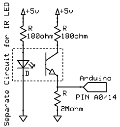
There is another option that should be mentioned here. A small 5 volt relay is available that can connect to the Arduino. If you use these, make sure they have (or you use) a freewheeling diode and optocoupler to protect the Arduino.

This particular example can be cycled 100,000 times and switches 10 amps at up to 250 VAC. The optocoupler ensures that the Arduino is protected. It basically connects the Arduino to the relay via light. It uses an LED that activates a photo-transistor, all inside a small chip. It also ensures that only a few milliamps will be drawn from the Arduino output .


I would not recommend paralleling relay boards, though. When they activate, they don't turn on at exactly the same speed. This means that one may turn on a few micro seconds before the rest. That one set of electrical contacts will be temporarily carrying the entire load. Let's say that you have a 100 amp load and you are using 10 relays each capable of 10 amp switching. Then, for those few initial micro seconds, one relay is carrying 100 amps. This will start to burn out the contacts, or worse, weld the contacts closed. That would be very bad for a dump load controller. It would drain your batteries and kill them. And we don't harm batteries here...not here...ever.


IF YOU'RE INTERESTED IN LEARNING ELECTRONICS 
Then Take A Look At This!

Sunday, January 3, 2016

Arduino: Micro Processing Renewable Energy - Part 3 - Measuring RPMs

Measuring RPMs

Let´s face it, sometimes we just need to know how fast something is spinning. Sure, we can eyeball it to some extent, up to a few hundred RPMs, but after that it becomes a little bit hairy. And, even then, it isn´t very accurate. The Arduino is perfect for quick and easy projects like this, when you just need to do some quick tests.

Measuring RPMs is basically just counting pulses per revolution over a given time frame and extrapolating out to one minute. But, what pulses and how do we do it? There are many ways I can think of, but two very common methods are used; hall effect sensors and optical (photo interrupters). So, let´s dive right in.

Hall Effect Sensor

A hall effect sensor works on changes in magnetic fields. Basically, if you have a magnet attached to the rotating object that you want to measure, every time it passes the hall sensor, a voltage is created on the output. The Arduino can detect the change and count it as a pulse. If you get 50 pulses per second, for example, that equates to 3,000 RPMs.


You can use a circuit board like this one and it will work fine. You could also use the hall sensor directly, as shown below. The 10k resistor is a pull-up resistor to keep the normal out put state high or close to 5 volts in this case. When the hall sensor is triggered, the output goes down.


Something to keep in mind is balance. Putting one magnet on a high speed rotating device might make it out of balance. You could consider putting two magnets on the rotor across from each other to balance it. Opposite poles could be pointing out to make the changes in poles more distinct and to give better accuracy.

Optical Photo Interrupter

This one is like it sounds, you are interrupting a beam of light. Typically, these use a rotary encoder disc which are discs with slots cut out.


The optical sensor sits straddled over the disk. A built-in diode shines a light while a photo-transistor senses that light. An On or Off signal is then generated for the Arduino.

Image courtesy of utopiamechanicus.com

Be aware that you don´t need a disc with this many slots cut in it, especially when measuring high RPMs. For low RPMs, the example above would be perfect and very accurate. But for higher RPMs, something like this would be much better.


IF YOU'RE INTERESTED IN LEARNING ELECTRONICS 
Then Take A Look At This!